Transistor-only LED flasher
2020-10-01
The LED flasher is the “hello world” of electronics. The circuit typically uses an RC circuit consisting of a capacitor charging and discharging repeatedly through a resistor for timing.
Here’s my slightly unusual take on it. The entire circuit consists solely of 6 transistors. There are no other components at all. How does it keep time?

The core of the circuit is a simple integrator – a current source charging a capacitor. A voltage-controlled switch discharges the capacitor when the voltage reaches a threshold.
To make this circuit compact and transistor-only, I had to use several different kinds of transistors, and abuse some of the lesser-known properties of each. Here are the tricks involved:
-
The integrator capacitor is formed by the parasitic capacitance of two MOSFETs, Q2 and Q6.
Parasitic capacitances are usually undesirable, so manufacturers go out of their way to minimise them. In our case the capacitance is on the order of 100pF, which is really quite tiny. We’ll need an equally tiny current to achieve a second-long flashing period.
-
The current source is actually the reverse leakage current through a BJT, Q3. This can be on the order of 100pA, which is tiny – perfect for our application.
The transistor can be any jellybean BJT; NPN or PNP. Some experimentation is required to find one with the right leakage current. Be careful not to exceed the reverse breakdown voltage.
-
The threshold detector is formed of Q6 and Q4, two inverting amplifiers (or, looked at another way, NMOS not gates) back to back. I use the output of this to turn on a discharge MOSFET when the threshold is crossed.
-
These two inverting amplifiers are open-collector, so we need some kind of weak pull-up for each. Conventionally we’d use resistors, but in this case we have the JFETs Q5 and Q1, taking advantage of the property that JFETs act like a constant current source at VGS = 0.
-
Conveniently, the amplifiers also give us current amplification, so we can simply stick our LED D1 into the current path. Now the pull-up JFET Q5 also serves as a current limiter for the LED; pick one that gives 1mA or so.
-
For the discharge MOSFET Q2, I deliberately picked a beefy power MOSFET for its higher parasitic gate capacitance. As the MOSFET discharges the integrator capacitor, the voltage-controlled switch wants to turn it off again. The gate capacitance on the MOSFET makes it react slower to this, which helps it stay turned on for longer, discharging the capacitor more completely, and leading to a slower flashing frequency.
| Front: |
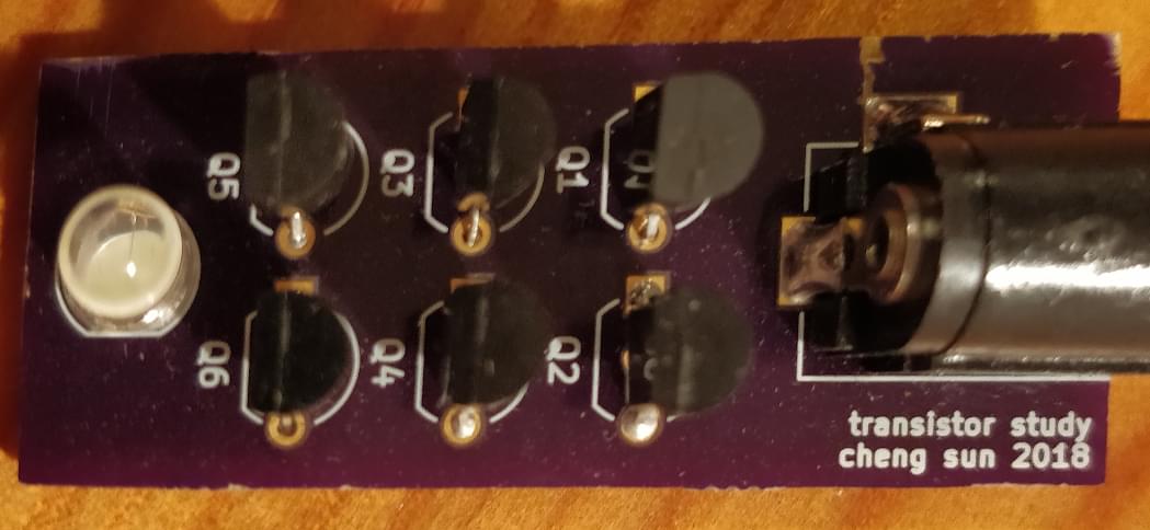
|
| Back1: |
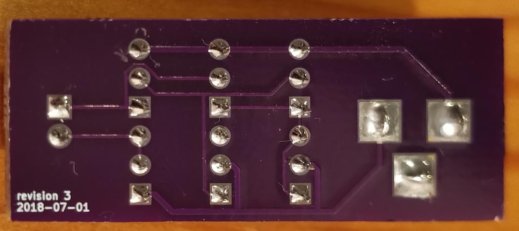
|
| Layout: |
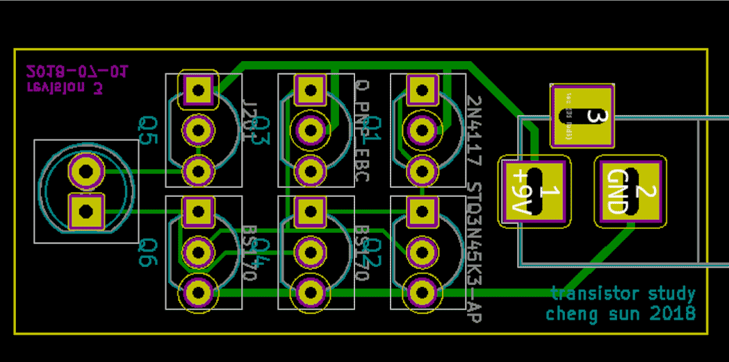
|
-
I designed this circuit quite some time ago: the back of the PCB has 2018-07-01 printed on it. It took a while for me to get round to writing this up. ↩